What Robot Developers Should Check Before Selecting Bevel Gearboxes
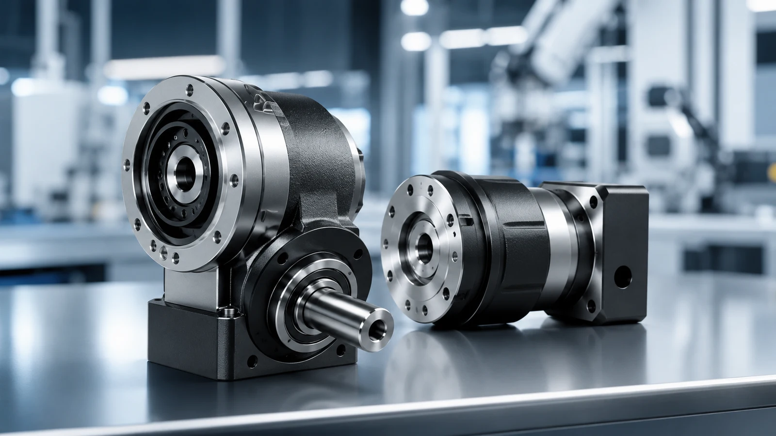
English translation from Unibot. Source published 2026-06-11.
In real projects with bevel gearboxes, the main problems most often arise not because of the type of transmission itself, but because of the inconsistency between the requirements for the unit, the design of the supports and the acceptance criteria.
Start with the requirements for the unit, not with the choice of gearbox
When robot designers select angular gearing (especially for wrists, elbows, waist, and legs), a common mistake is to start with a "popular gearbox" or a "high-performance gearbox" without translating the assembly's needs into measurable goals. Angular gearing is essentially a compromise between drivetrain layout/placement and performance.
Before you compare options, identify your site requirements in six groups. Each must take into account calculations, thermal limitations, assembly and acceptance criteria:
Torque and shock loads - peak torque, shock frequency, reverse shock events.
Speed and Duty Cycle - Continuous vs. Intermittent Positioning; heat accumulation.
Accuracy and stability - backlash, torsional rigidity, effect of transmission error on control.
Reversibility and safety - required behavior during reversal (learning, compliance in a collision) versus holding/self-braking.
Service life and maintenance - lubrication method, sensitivity to contamination, maintainability.
System integration - dimensions, bearing arrangement, housing rigidity, assembly repeatability.
The corner assembly layout combines the transmission, bearings, and sensors into one assembly.
Practical road map: what each option solves
In engineering, angular gearing is rarely “good vs. bad.” It "qualifies for a specific limitation." The table below helps you quickly sift through your options and avoid dead ends.
Table 1. Quick comparison of solutions for angular gears (input table)
Option
Typical Strengths
Typical Limitations
Best uses (examples)
Bevel Gear (Straight/Helical/Hypoid)
High efficiency, compact single-stage 90° transmission, smooth movement
Sensitive to assembly settings (mounting position/play/contact patch), requires repeatable support stiffness
Nodes where efficiency and controlled temperature are needed; applications benefiting from reversibility and smoothness
Worm gear
High gear ratio in a compact body; can be designed for a strong hold
More slip → efficiency and heating are more critical; characteristics are highly dependent on lubricant and operating mode
Parts requiring hold/rollback protection, low speeds, acceptable efficiency loss and thermal load
Angular planetary gearbox or bevel+planetary gear combination
Higher torque density; backlash can be controlled through the design
More complex design; longer build/validation chain
Assemblies with medium to high torque, stiffness/play requirements and sufficient space
Precision gearbox (wave/cycloidal, etc.) + angular stage
High gear ratio and low backlash for positioning
Impact resistance, durability and reversibility feel vary by model and application
Actuators and precision positioning units (after checking shock loads, service life and reversibility)
Note: Wave/cycloidal gearboxes are not themselves "angular gears", but they are often combined with an angular stage to achieve both compactness and high gear ratios.
8 most important checks (in order of priority)
Here are eight points to confirm before choosing and check after. They are arranged in a practical sequence for design reviews.
1. Efficiency and Heating: Thermal History First
Robot nodes are rarely “single peak events.” They experience repetitive acceleration/deceleration and duty cycles. Heat is often the first limiting factor.
For high slip applications, small changes in lubrication and operating conditions can have a significant impact on efficiency and heating. In many robotic assemblies, the more efficient option provides a margin not only in temperature, but also in lubricant life and gap stability over time.
Robot nodes can combine several types of gears; here we focus on the corner step.
2. Reversibility: determine the “reverse torque window”
Reversibility is not a binary property. Define it as a window:
At target load and speed - do you need controlled rebound (learning, crash compliance)?
Or do you need a hold (rollback protection, power failure hold)?
Some kinematic schemes provide reliable self-braking, but often at the cost of reduced efficiency and increased heat generation. Quantify the flyback requirements: target torque range, speed and acceptable hysteresis.
3. Play and stiffness: indicate “play under load”
Control accuracy is affected by angular movement under load, and not just by the nameplate value of the play. Set three parameters (even approximately at the concept stage):
Backlash without load (during initial assembly).
Backlash at rated torque (taking into account elastic deformation).
Torsional stiffness (e.g. Nm/arcmin or Nm/rad).
If you only specify “small play” without reference to load, you will most likely miss what really affects the operation of the mechanism.
4. Assembly repeatability: the most underestimated risk
Whether you choose a helical bevel or hypoid gear, repeatability is highly dependent on the assembly settings and the stiffness of the supports. Treat this as drawing requirements and acceptance criteria:
Gear position (meshing depth).
Backlash (measured and recorded).
Contact patch (under specified test conditions).
The quality of engagement of bevel gears is determined by installation, backlash and rigidity of the supports.
5. Housing and bearings: right angle loads
Angular gears create multidirectional loads. The bearing pattern and housing rigidity determine:
Does the load cause edge contact or spot displacement.
Does thermal expansion exceed the permissible clearance limits?
Does repeatability vary from build to build?
Practical question to test: Does deflection under load cause edge contact in engagement?
6. Lubrication and seals: a common cause of loss of stability
Many right-angle gearboxes perform well in short-term testing, but begin to "float" in the field due to contamination, lubricant degradation, or changes in seal resistance. When choosing, clearly state:
Type of lubrication (grease or oil) and maintenance strategy.
Seal pattern and contamination risks.
How lubrication condition affects heating and torque drift over time.
7. Noise and Vibration: Determine Acceptable Limits
It is enough to set simple acceptance criteria:
Acceptable acoustic behavior (no abnormal whistles, periodic knocks).
No evidence of edge contact or hot gap collapse that could cause anomalies.
Then tie this to measurable tests: contact patch stability, backlash drift, and temperature rise.
8. Chain of custody and acceptance: demand evidence
To avoid receiving “seemingly good” details, request confirmations that correspond to the chosen scheme:
Reports on key geometric tooth profile measurements and assembly-critical surfaces.
Assembly protocols (gear position/backlash) and photos of the contact patch for bevel gears.
Batch traceability of critical parts (material/heat treatment/inspection, if applicable).
Decision Table: Put “Requirement → Schematic → Validation” together
This table is designed to be immediately inserted into a project review (DR) template and keep your team on track.
Table 2. Decision table for selecting angular gears (DR template)
Target result
Key Limitation
Priority Candidates
Be sure to check
High efficiency, controlled temperature, smooth return
High load, heat sensitive
Bevel gear (straight/spiral/hypoid) or angular planetary combinations
Temperature rise under load; repeatability of assembly (installation/play/spot); play and rigidity under load
Secure retention/reverse protection
Efficiency losses are acceptable
Worm gear (confirm self-braking in your conditions)
Temperature rise/efficiency trend; reverse torque window; lubrication stability
High positioning accuracy, low backlash
Precision control is a priority
Precision gearbox + angular stage; or low-backlash design solutions
Play under load; torsional rigidity; resource strategy for a given cycle
Frequent shock and reverse loads
Impact resource is a priority
Combined circuits with a large margin of safety
Increase in backlash during impacts; stability of load/contact distribution under load
Practical pitfalls: three easily missed mistakes
Indication of "small backlash" without load conditions. Most handling problems occur under torque and heat, not under no-load conditions.
Acceptance for smooth running without load without checking stability under load. For bevel gears, check mounting/backlash/spot repeatability and confirm no drift under thermal conditions.
Ignoring the thermal cycle. A route that has passed short tests can “float away” under real workload. Heating accelerates lubricant degradation and changes in clearances, and this affects productivity and repeatability.
Conclusion
Choosing an angular gear for a robot is not just about choosing the type of gearbox. It's safer to do this:
Break down articulation requirements into measurable metrics.
Weed out options using a clear route map.
Strengthen performance and repeatability with acceptance testing.
If efficiency/heating, reversibility, loaded backlash and stiffness, set-up repeatability (for bevel gears), lubrication and seals, and bearing stiffness are factored into the design and acceptance phase, most late rework can be prevented in the early stages.